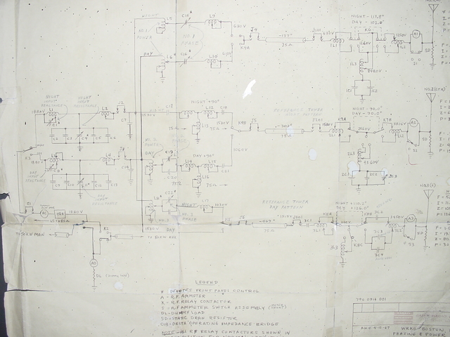
Taped to the left side of the phasor cabinet is a hand-drawn paper circuit diagram, showing the design of the entire antenna system from the output of the transmitter to the three towers.
Copyright 2004, Garrett Wollman. All rights reserved. Photograph taken 2004-05-06.